Effective Isotropic Radiated Power (EIRP) explained
Sat 05 August 2023 by Gioacchino CastorioIn this post, I would like to discuss a topic that, surprisingly, has kept coming over and over in the discussions with my customers: the difference between the concepts of Transmit (TX) Power and the Effective Isotropic Radiated Power (EIRP). People tend to confuse the two terms and this create a lot of headaches when it comes to troubleshooting tickets relating to poor signal quality.
Glossary
Let's clarify immediately some of the terms that will show up later in the post:
- TX Power: it is the amount of power measured in Watts (W) at the output of a transmitter.
- Loss/Attenuation: it is the decrease of strength in a signal propagating through a physical medium. An example is Free-Space Path Loss (FSPL) is observed at the receiver after the signal propagates through free space (normally air) and it increases with the distance between the transmitter and the receiver. Cables and waveguides introduce losses.
- Isotropic Antenna: it is a point antenna transmitting, and receiving, signal equally in all directions. It is impossible to create such an antenna in real life, so we use it as a reference.
Antenna Gain
The Antenna Gain is the increase in transmitted (or received) signal strength due to the antenna focusing the RF energy towards a direction. This gain is passive as the antenna does not add more external power to the signal as an RF amplifier would (i.e. we do not need to power up an antenna). The direction of maximum gain is usually called Antenna Boresight.
The gain G is an adimensional scalar computed as a ratio:

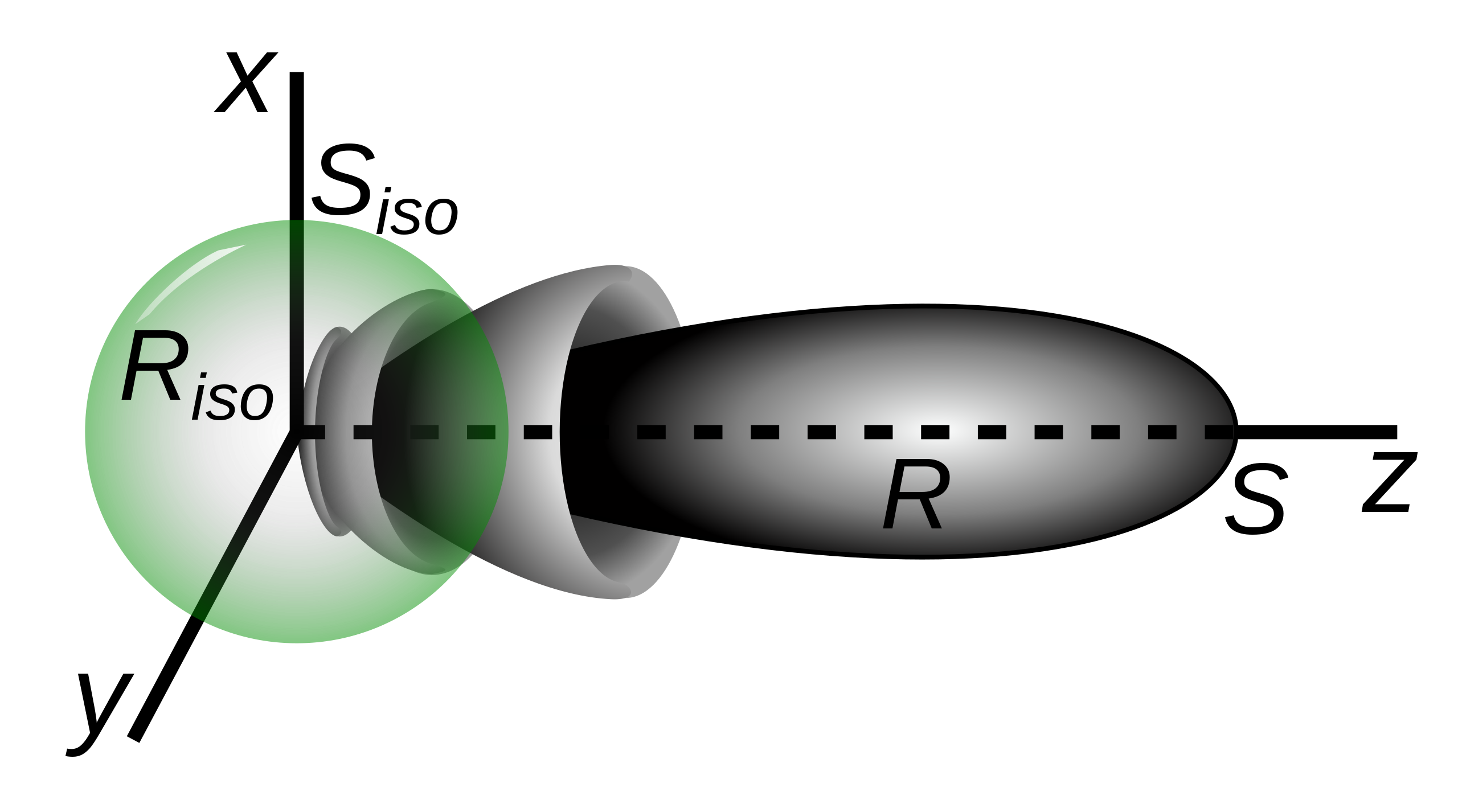
where Prx,i is the power of a sample signal received at an isotropic antenna, while Prx is the power of the same sample signal received at the antenna for which we are computing the gain. The Wikipedia article describing Atenna Gains shows the image below (public domain) to represent how a directional antenna radiates the same power as an isotropic radiator while focusing it on a specific direction:

In the logarithmic scale, the gain is expressed in dBi (with 0 dBi meaning that the antenna is isotropic as the ratio equals 1).
Computing the EIRP
In my previous blog post Introduction to RX-SOP Configuration, I already described at a high level how to compute the power at the receiver (RX) when the only relevant effect is FSPL, but I abused the notation Ptx to refer to the power at the transmitter antenna. I should have used the EIRP, which is defined as follows:

where PTX is the TX Power, Gtx,i is the transmit antenna gain with respect to the isotropic antenna, Gtxbf is the transmit beamforming gain, and Lc is the loss due to the cable between the transmitter and the antenna. The beamforming gain is obtained in a Multiple-Input Multiple-Output (MIMO) system that focuses the RF power on a specific direction combining the effect of multiple antennas transmitting at the same time with a constructive effect. The EIRP formula can be expressed in decibels-to-milliwatt (dBm) as follows:

It is common to find in datasheets and regulatory domain documents EIRP values expressed as a number in dBm followed by e.i.r.p. (for instance, 20 dBm e.i.r.p.).
Why does EIRP matter?
Now that the reader has a clearer idea of what EIRP is and how it correlates to the TX power, we can explore how these two concepts influence our day-to-day.
ETSI EN 300 328 v2.2 Section 4.3.2.2.3 set the power limit for non-Frequency Hopping Spread Spectrum wideband data transmission equipment, such as 802.11 stations to be less or equal to 20 dBm e.i.r.p. in Europe. Section 5.3.2.2.4 further specifies that in case a beamforming gain exists, it should be taken into account for testing the equipment in the ETSI domain.
The above represents a constraint to the maximum TX power our APs can use. Once we pick an antenna for our station, we will need to guarantee that the TX power and the Transmit Beamforming gain (if the latter is used in the transmission) stay within the specified limit. For instance, if our AP has an internal antenna (no cable loss) with a 5 dBi and we know we get a 3 dB beamforming gain in our transmission, then the maximum TX power in Europe must be less or equal to 12 dBm.
References
- Coleman D.D., Westcott D.A. CWNA Certified Wireless Network Administrator Study Guide: Exam CWNA-107, Chapters 3 and 4, 5th Edition: Sybex. 2018.
- Haykin S., Moher M. Communication Systems, Chapter 6, 5th Edition: Wiley. 2010.
- Gain (antenna). (2023, March 28). Wikipedia. https://en.wikipedia.org/wiki/Gain_(antenna)
- ETSI, EN. "300 328 V2. 2.2 (2019-07)." Wideband transmission systems (2019).