Demystifying modulation techniques with BPSK
Tue 18 April 2023 by Gioacchino CastorioThe multitude of Modulation and Coding Schemes (MCSs) introduced in IEEE802.11 for the VHT and HE PHYs may look like magical spells even for the seasoned wireless engineer. At the start of my journey as a telecommunications engineer, I was particularly fascinated by the mathematics behind how to carry information from a transmitter (TX) to a receiver (RX). I believe it might be worth it to take a step back and get a mathematical intuition of what is happening behind the scenes when a STA interacts with the wireless medium.
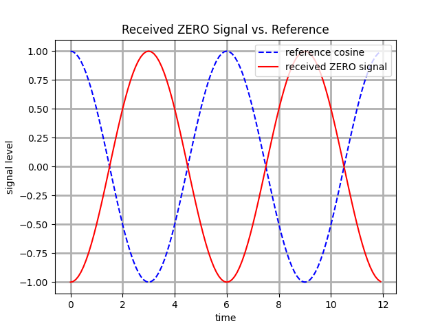
Assuming we can transmit the signal wave s(t), as in the equation below, where A is the amplitude, f is the signal frequency, and the time, we could consider representing 1's as s(t) and 0's as -s(t).

The receiver station would immediately recognise what value we are transmitting by comparing what is received with the reference signal, which is assumed to be known. The figure below shows the comparison between the reference signal and what can be seen at the receiving station, considering path loss exclusively and ignoring additional effects such as multipath; the picture shows a "one" being received, followed by a zero.
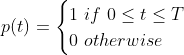
The carrier signal s(t) is not enough to transmit any meaningful information in real life: the time variable t is an infinite real number and s(t) repeats periodically with no start or end in time. We are busy people, and we want to transmit more than one bit in perpetuity: we can define a new rectangular function p(t) which is not-null only for 0 <= t <= T, where T = 1/f is the "period" of the signal s(t).
Multiplying the two functions g(t) = s(t)p(t), we get a limited section of the the original signal, namely a cycle of the cosine wave.
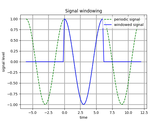
This signal p(t) is extremely powerful because it lets us move its "windowing" effect by simply shifting its "up" value by the period T to the left or right over the time axis so that p(t-kT) = 1 for kT <= t <= (k+1)T, where k is any integer number. We can shift the pulse g(t) by kT as well.
The windowed signals can be juxtaposed to represent a sequence of 0's and 1's fairly easily. The resulting signal can be described mathematically as a summation S(t), where N is the number of windows and the coefficient c is 1 when transmitting a "one" bit, -1 otherwise.
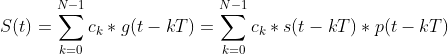
The following image shows an example of the application of the above formula when transmitting a zero followed by a one; the receiver can compare its local reference to the received signal. Note that this example considers the existence of some attenuation at RX due to Free Space Path Loss while ignoring other detrimental effects such as multi-path.
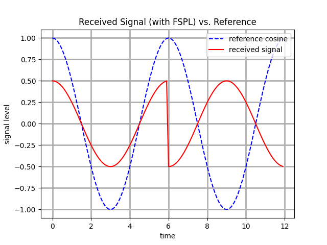
You might have noticed that some level of time synchronisation is needed between the reference and the received signal to allow effective demodulation. This fact is true regardless of the modulation technique in use, and it intuitively justifies the existence of preamble sequences in the IEEE802.11 PHY Protocol Data Units (PPDUs).
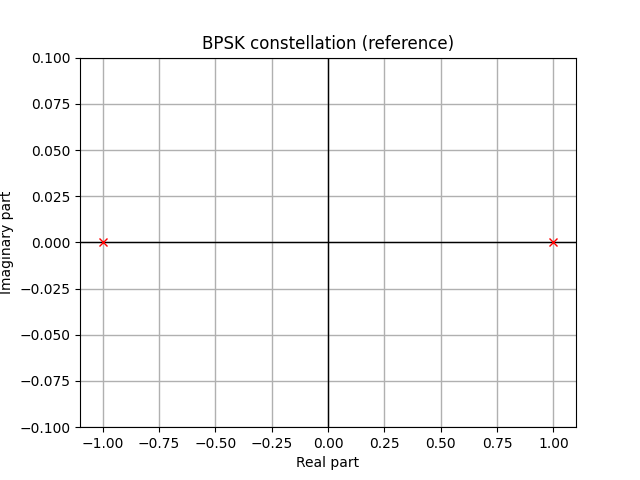
In conclusion, we managed to transmit a sequence of single bits leveraging the simple fact that our RX can discriminate between a positive or a negative coefficient for the signal. We defined a signal constellation containing two points which are shifted 180 degrees between each other: this technique is commonly referred to as Binary Phase Shift Keying (BPSK) because the same base carrier s(t) can assume two different phase configurations to represent a single bit.
Intuitively, we can expand the number of transmitted bits by following the same principles of "tweak a parameter and compare to a reference" as described above. We will explore Amplitude Shift Keying (ASK), Quadrature Phase Shift Keying (QPSK), and Quadrature Amplitude Modulation (QAM) in future blog posts.
Until next time!
Bibliography
- Moher, Michael, and S. Haykin. Communication Systems, 5th ed, Chapter 4. Wiley, 2010.
- Carpenter, T. CWAP-404: Certified Wireless Analysis Professional, Chapter 3. Certitrek Publishing, 2021